Step 1. We are given the two loads of 3 kN / kNmm and at a distance of 3m each. We are asked to draw the shear and moment diagrams for the beam. Step 2. The free-body diagram of the beam can be drawn as: Here, Ax is the horizontal component of support A, Ay is the vertical component of support A and NC is the normal force reaction at support C.
Biological Material Interfaces as Inspiration for Mechanical and Optical Material Designs | Chemical Reviews
SOLUTION. 1- Draw the FBD of the beam. In the FBD, the directions of the unknown force and moment are assumed positive according to the member sign convention. 2- Solve the equations of equilibrium for the support reactions. 3- Make a cut in the FBD of the beam at an arbitrary point x meter away from the left end of the beam as shown.

Source Image: transtutors.com
Download Image
Step-by-Step Solution. Step 1. We are given the load P = 10 kN/m P = 10 k N / m, moment M = 20 kN⋅ m M = 20 k N ⋅ m and force is F = 15 kN F = 15 k N. We are asked to draw the shear and moment diagrams. Step 2. The reaction force on the load is calculated as: R = P ×d1 R = P × d 1.

Source Image: m.youtube.com
Download Image
SOUNDS LIKE BRANDING™ » Blog » The impact of music on businesses in public places #1
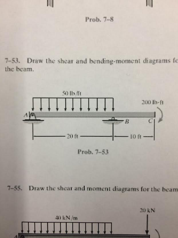
Step 1 We are given the distributed load on section AB is w = 50 lb/f t w = 50 l b / f t, and the moment at point C is M = 200 lb⋅f t M = 200 l b ⋅ f t. We are asked the shear and bending moment diagrams for the beam. Step 2 The free body diagram of the system is: We have the distance between points A and B is AB = 20 f t A B = 20 f t.

Source Image: chegg.com
Download Image
7-53 Draw The Shear And Moment Diagrams For The Beam
Step 1 We are given the distributed load on section AB is w = 50 lb/f t w = 50 l b / f t, and the moment at point C is M = 200 lb⋅f t M = 200 l b ⋅ f t. We are asked the shear and bending moment diagrams for the beam. Step 2 The free body diagram of the system is: We have the distance between points A and B is AB = 20 f t A B = 20 f t.
Shear and Moment Diagrams. Shear and Moment Diagrams. Consider a simple beam shown of length L that carries a uniform load of w (N/m) throughout its length and is held in equilibrium by reactions R 1 and R 2. Assume that the beam is cut at point C a distance of x from he left support and the portion of the beam to the right of C be removed.
Solved Draw the shear and bending moment diagrams for the | Chegg.com
6—25. Draw the shear and moment diagrams for the beam– The two segments are joined together at B. 8 kip 3 kip,ft 5 ft *6—20. Draw the shear and moment diagrams for the beam, and determine the shear and moment throughout the beam 10 kip 2 kip/ft g Kip 8 kip 40 kip.ft as functions of x. Support Reactions: As shown on FBD. Shear and Moment
SOLVED: 7-53. Draw the shear and moment diagrams for the beam Problem 7-53 20 kN 40 kN/m B 150 kNm 8 m 3 m

Source Image: numerade.com
Download Image
PDF] Design optimisation of steel portal frames using modified distributed genetic algorithms | Semantic Scholar
6—25. Draw the shear and moment diagrams for the beam– The two segments are joined together at B. 8 kip 3 kip,ft 5 ft *6—20. Draw the shear and moment diagrams for the beam, and determine the shear and moment throughout the beam 10 kip 2 kip/ft g Kip 8 kip 40 kip.ft as functions of x. Support Reactions: As shown on FBD. Shear and Moment
![PDF] Design optimisation of steel portal frames using modified distributed genetic algorithms | Semantic Scholar](https://d3i71xaburhd42.cloudfront.net/d09d66081ed72ec15a5323ab0efb57a46ca07057/63-Figure2-7-1.png)
Source Image: semanticscholar.org
Download Image
Biological Material Interfaces as Inspiration for Mechanical and Optical Material Designs | Chemical Reviews
Step 1. We are given the two loads of 3 kN / kNmm and at a distance of 3m each. We are asked to draw the shear and moment diagrams for the beam. Step 2. The free-body diagram of the beam can be drawn as: Here, Ax is the horizontal component of support A, Ay is the vertical component of support A and NC is the normal force reaction at support C.

Source Image: pubs.acs.org
Download Image
SOUNDS LIKE BRANDING™ » Blog » The impact of music on businesses in public places #1
Step-by-Step Solution. Step 1. We are given the load P = 10 kN/m P = 10 k N / m, moment M = 20 kN⋅ m M = 20 k N ⋅ m and force is F = 15 kN F = 15 k N. We are asked to draw the shear and moment diagrams. Step 2. The reaction force on the load is calculated as: R = P ×d1 R = P × d 1.

Source Image: soundslikebranding.com
Download Image
The stadium wave | Climate Etc.
Plots of V(x) and M(x) are known as shear and bending moment diagrams, and it is necessary to obtain them before the stresses can be determined. For the end-loaded cantilever, the diagrams shown in Figure 3 are obvious from Eqns. 4.1.1 and 4.1.2. Figure 4: Wall reactions for the cantilevered beam.

Source Image: judithcurry.com
Download Image
Insights from New MH370 Tracking Data « MH370 and Other Investigations
Step 1 We are given the distributed load on section AB is w = 50 lb/f t w = 50 l b / f t, and the moment at point C is M = 200 lb⋅f t M = 200 l b ⋅ f t. We are asked the shear and bending moment diagrams for the beam. Step 2 The free body diagram of the system is: We have the distance between points A and B is AB = 20 f t A B = 20 f t.

Source Image: mh370.radiantphysics.com
Download Image
More Bender on Hurricane Counts | Climate Audit
Shear and Moment Diagrams. Shear and Moment Diagrams. Consider a simple beam shown of length L that carries a uniform load of w (N/m) throughout its length and is held in equilibrium by reactions R 1 and R 2. Assume that the beam is cut at point C a distance of x from he left support and the portion of the beam to the right of C be removed.

Source Image: climateaudit.org
Download Image
PDF] Design optimisation of steel portal frames using modified distributed genetic algorithms | Semantic Scholar
More Bender on Hurricane Counts | Climate Audit
SOLUTION. 1- Draw the FBD of the beam. In the FBD, the directions of the unknown force and moment are assumed positive according to the member sign convention. 2- Solve the equations of equilibrium for the support reactions. 3- Make a cut in the FBD of the beam at an arbitrary point x meter away from the left end of the beam as shown.
SOUNDS LIKE BRANDING™ » Blog » The impact of music on businesses in public places #1 Insights from New MH370 Tracking Data « MH370 and Other Investigations
Plots of V(x) and M(x) are known as shear and bending moment diagrams, and it is necessary to obtain them before the stresses can be determined. For the end-loaded cantilever, the diagrams shown in Figure 3 are obvious from Eqns. 4.1.1 and 4.1.2. Figure 4: Wall reactions for the cantilevered beam.